 DISCOVERY SCIENCE CENTER
|
|
|
|
Steam-Powered Four-Stroke Engine Objectives: The four-stroke engine design has been used in the production of automobiles, trucks, motorboats and much other equipment that requires a powerful rotary motion. It is a fundamental topic for the teaching of such vehicles. The basic concept has not changed since its first introduction as an engine for cars.
In the teaching of the four-stroke engine to students of Physics for Form 4, as well as that of General Science for Form 5, it has been a difficult task to convey the concept of the need for the various strokes, the concept of motion generation, as well as the notion of converting up-down motion into rotary motion. These complicated concepts are puzzling to students who encounter them for the first time.
Many text-books have fabricated line drawings to describe these functions. However, they are one-dimensional are thus impossible to use to convey the concept of motion generation. They can at best be used to label the various parts, as well as to set questions. This method is the only way for students to answer examination questions.
Many hand-operated models have been produced by laboratory suppliers as teaching aids. They work well to demonstrate the functions of the various strokes of the engine operation. However, they do not convey the concept of automatic motion, and the source of power in the engines.
Using real engines is a messy task, not to mention the costs and maintenance that are involved. The generation of petrol exhaust is also hazardous to health in a closed laboratory. Students would not be able to study the engines for an extended period of time because of the smell generated. Handling petrol can also be a fire hazard.
We wanted to build a working model to demonstrate the working of the four-stroke engine that uses materials that are easily available at low or no cost. It has to be environmentally friendly, and safe to use. It has to be a working model to be able to demonstrate the concept of motion generation, the power stroke, and the conversion of up-down motion into rotary motion.
Steam is environmentally clean, and easily produced. It can be used to show the concept of the power of expansion, which is the crux of source of power in the power stroke of the four-stroke cycle. The source of aluminium cans is to be found in almost every home. With the correct techniques, it is easy to work on without the use of any heavy equipment or tools.
Apparatus/materials The construction of the engine block requires the following tools and materials:
The setup of the apparatus include
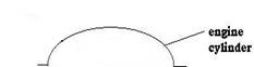
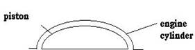
Construction of the engine block
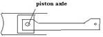
b. Cut another aluminium can in half to obtain a semicircular cross-sectional shape that fits into the engine cylinder. A piece of aluminium should be to form the axle for the piston rod.
The cutting should be such that the movement can be continuous in a circular motion for the flywheel.
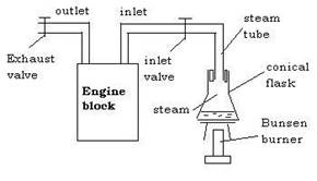
Using the engine block Using the engine block involves mounting the engine onto two retort stands to allow the engine to function in a vertical manner. The steps in setting up the apparatus are as follows: a. Set up a steam generating apparatus using a conical flask mounted on a tripod stand and gauze, and using a Bunsen burner to heat the water. To use a 250 ml flask, 100 ml of water is sufficient. b. Direct the steam into the inlet valve of the engine until there is enough steam to push the piston down. This demonstrates the power stroke of the engine. The whole setup can be seen in the following picture: 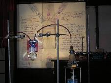
a. It takes some practice to be able to direct the steam into the engine at the moment the engine is in the power stroke. b. It is necessary to remove the supply of steam before the end of the power stroke. c. The valve of the exhaust tube should be removed at the start of the exhaust stroke. N.B. It is to be noted that the current design of the engine does not involve any action to be taken during the induction and compression strokes.
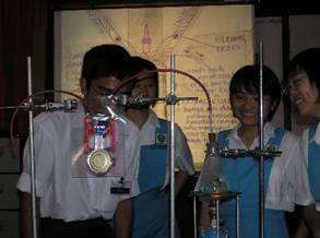
The following picture shows students working on the apparatus:
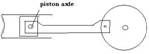
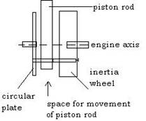
The construction of the inertia wheel The construction of the inertia wheel involves the attachment of a heavier wheel to the axle of the engine. The design of the mechanism is shown in the following diagram:
There must be a space for the piston rod to move up and down and in a circular movement. Hence the circular plate needs to be mounted separately from the inertia wheel. The weight of this inertia wheel should be heavy enough for the circular motion to be maintained. Without this inertia wheel, the power stroke just pushes the piston down, and there is not enough inertia to carry the piston upwards in the upstroke. 2. Implementation
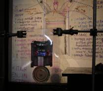
The implementation consists of the use of dynamic transparencies such as the following:  Two sets of transparencies should be produced, one for the 4-stroke petrol engine, and one for the 4-stroke diesel engine.
The teaching method involves the following steps:
3. Results and Benefits
A) The apparatus can be used to show the functions of a) four-cycle petrol engine b) four-cycle diesel engine c) the use of valves to control the flow of gases
B) The concepts learned include: a) The force of expanding gas b) How motion is generated in a combustion engine
C) The advantages of this apparatus includes the flowing: a) The construction is simple b) The materials are easily obtainable c) Students can observe the force that is generated during the power stroke of the engine d) The use of inertia in the inertia wheel, which is the flywheel, to ensure continuous rotation.
D) Future Enhancements The current design is just the beginning of research and development to produce an apparatus to show the full cycle of the four-stroke engine. Future enhancements include the following: a) A better method of generating steam for the power stroke b) An automatic system for controlling the inlet of steam during the power stroke. (The current design requires some manual skills in controlling the steam inlet).
|
|
Send mail to
zhiq@pc.jaring.my with
questions or comments about this web site.
|